2 Level Calculation
Requisitos de finalización
2.2 Absolute and relative Levels
For level
information there are two options, which depend on the reference value used.
The relative level is the ratio of two electrical quantities,
In contrast, if the magnitude A of a physical quantity at any point of a transmission system is based on a fixed (normed) reference value A0 (rated value), with DIN 5485 it is called absolute level
\( L_{abs} = 10\text{lg} \frac{A}{A_0} \) in dBx. (2-12)
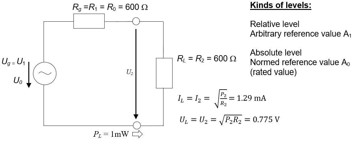
Figure 2-3: International reference system for absolute levels.
The relative level is the ratio of two electrical quantities,
- most often the ratio of output to input value A2/A1 (This quotient of output and input quantity accommodates the fact that in practice often not output but input is the reference value) or
- between two distinct points, e.g. point 1 and point 2 of the transmission system in Figure 2-1 or
- in general, the signal value A2 at one point of the transmission system in relation to an arbitrarily chosen reference value A1,
In contrast, if the magnitude A of a physical quantity at any point of a transmission system is based on a fixed (normed) reference value A0 (rated value), with DIN 5485 it is called absolute level
\( L_{abs} = 10\text{lg} \frac{A}{A_0} \) in dBx. (2-12)
These reference values are obligatory definitions of the so called international reference system (Figure 2-3) consisting of a voltage source with generator resistance Rg = R0 = 600 Ω. feeding exactly 1 mW of power into a load resistance of RL = 600 Ω. The values of current and power at the effective resistance are the “normed rated values”, the same as effective resistance and power. Often they are characterized by the index „0“.
Figure 2-3: International reference system for absolute levels.