7 Network Functions
Completion requirements
7.2 Handover
One task
directly resulting from mobility and cellular structure is handover. If a user has access to a
service while crossing a cell border he/she should not experience any
disruption (seamless handover). Therefore, a new radio connection to
another cell has to be setup without interaction of the user.
The number of handovers increases with decreasing cell size, and frequent handovers decrease system efficiency.
Handover is the transfer of an ongoing connection (of the same radio network) inside the same cell (intra-cell handover) or from one cell to another (inter-cell handover). The aim of the handover is to cope with mobility and to avoid lacks of quality. At the same time the total performance of the system has to be ensured, e.g. by avoidance of distortions to the connections by interference or routing problems in the fixed network. Not only the quality of each single connection, but as well that of the network is increased by handover. Overload in single cells can be avoided by dynamically assigning cells. This increases network economics. Therefore, the handover can have different reasons:

In GSM
there is only one type of handover, hard handover. That means the connection to
the old BS is terminated before the connection to the new BS is setup. The
disruption lasts about 0.01 ms resulting in a loss of up to two data frames
that have to be retransmitted.
In UMTS two other handover types are defined, but they cannot be used for handovers between different networks or providers.
Soft handover means that there are simultaneous connections to more than one BS, contained in an Active Set of up to six connections. In that way data loss can be avoided and even diversity gain is achievable. But this scenario causes long routes in the network. Thus, the anchor point of the RRC connection between UE and RNC is changed via relocation procedure, if routing in UTRAN can be optimized. This function is also in use with hard handover.
Soft Handover is not possible every time, e.g. if the Iur interface between RNCs is not available (an interface between GSM BSCs is not defined) or if the handover is between different RNCs. It is also impossible, if the frequency has to be changed or the UMTS mode changes from FDD to TDD or vice versa.
A subtype of soft handover is softer handover, where all cells of the Active Set belong to one Node B.
UMTS simplifies the handover control by using only one procedure for circuit and packet switched calls (different to GSM). In GPRS there is no permanent connection between the MS and the network. Only a session is installed, it uses no radio resources if not active. In active mode temporary resources are used. Thus, GPRS can adapt to applications with long pauses and it avoids continuous attach and detach and enhances frequency efficiency. In UMTS the connection is kept independent of the type of service.
Very interesting is the handover between UMTS and GSM. To enable measurements in different networks each GSM cell sends information about neighboring UTRAN cells (especially UTRAN/FDD as it is the normal UMTS mode of operation). This information contains among others carrier frequency and scrambling code. The UTRAN/FDD sends the ARFCN (Absolute Radio Frequency Channel Number) and BSIC (Base Station Identity Code) of the neighboring GSM cells.
The cell selection criteria are similar to those in GSM, received signal strength of the new cell has to be above a threshold and above the received signal strength from the serving cell.
In packet switched connections handover starts with the update of the routing area (RA) independent of the fact if it is necessary to change the RA. If the SGSN changes also PDP (Packet Data Protocol) context attributes are handed over. That way the new SGSN gets the IMSI. In circuit switched mode the context transfer is not necessary.

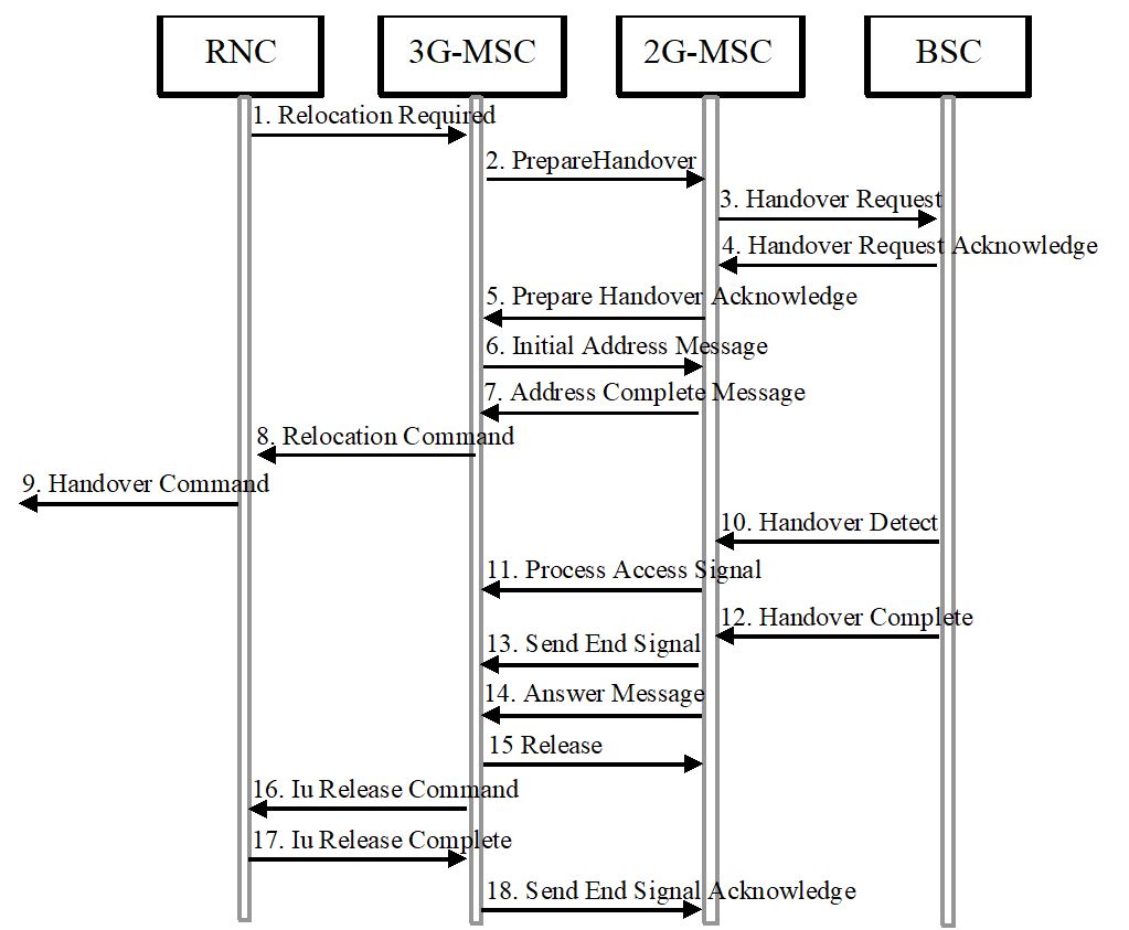
Figure 7-10: Handover from UMTS to GSM.
The number of handovers increases with decreasing cell size, and frequent handovers decrease system efficiency.
Handover is the transfer of an ongoing connection (of the same radio network) inside the same cell (intra-cell handover) or from one cell to another (inter-cell handover). The aim of the handover is to cope with mobility and to avoid lacks of quality. At the same time the total performance of the system has to be ensured, e.g. by avoidance of distortions to the connections by interference or routing problems in the fixed network. Not only the quality of each single connection, but as well that of the network is increased by handover. Overload in single cells can be avoided by dynamically assigning cells. This increases network economics. Therefore, the handover can have different reasons:
- Decreasing field strength
- Large RF phase jitter
- Data jitter
- High bit error rate
- Increasing amount of needed error correction
- Increasing distance to the transmitter (timing advance to high)
The
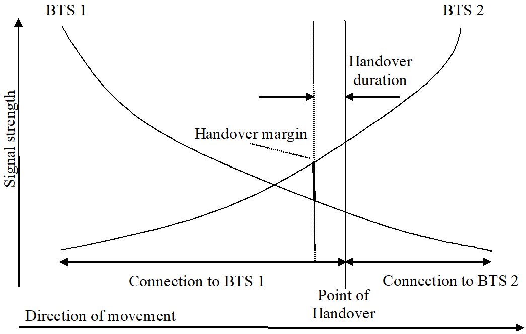
decision is based on measurements. The operator defines the measurements in
terms of frequency of measurements, collected data and the measuring network
element. In uplink the BS measures the signal level RXLev and the performance
of the received signal RXQual. In downlink the MS measures these data and data
of received levels from other stations. The MS sends these data to the BS every
480 ms. The BS takes all data into consideration. It averages values to
overcome fading. The averaged values are compared to thresholds. If the
threshold is achieved a new target cell is searched using the data collected by
the MS continuously. The handover usually only is initiated if the target cell
provides a significantly (6 dB) higher received field strength than the serving
cell. The algorithm depends on the operator. In addition, a hysteresis can be
implemented to avoid ping-pong handover, e.g. frequent handover between adjacent
cells if the user moves along their border.
Figure 7-7: Handover decision.
The
decision criteria for handover need to work even if the signal to noise ratio
is low and the propagation conditions are hard. They have to consider up- as
well as downlink. The computational and signaling effort has to be kept low. Specifications
for handover can be found in different standards, in GSM e.g. GSM 03.09, 04.08,
05.08 and 08.08.
In UMTS two other handover types are defined, but they cannot be used for handovers between different networks or providers.
Soft handover means that there are simultaneous connections to more than one BS, contained in an Active Set of up to six connections. In that way data loss can be avoided and even diversity gain is achievable. But this scenario causes long routes in the network. Thus, the anchor point of the RRC connection between UE and RNC is changed via relocation procedure, if routing in UTRAN can be optimized. This function is also in use with hard handover.
Soft Handover is not possible every time, e.g. if the Iur interface between RNCs is not available (an interface between GSM BSCs is not defined) or if the handover is between different RNCs. It is also impossible, if the frequency has to be changed or the UMTS mode changes from FDD to TDD or vice versa.
A subtype of soft handover is softer handover, where all cells of the Active Set belong to one Node B.
UMTS simplifies the handover control by using only one procedure for circuit and packet switched calls (different to GSM). In GPRS there is no permanent connection between the MS and the network. Only a session is installed, it uses no radio resources if not active. In active mode temporary resources are used. Thus, GPRS can adapt to applications with long pauses and it avoids continuous attach and detach and enhances frequency efficiency. In UMTS the connection is kept independent of the type of service.
Very interesting is the handover between UMTS and GSM. To enable measurements in different networks each GSM cell sends information about neighboring UTRAN cells (especially UTRAN/FDD as it is the normal UMTS mode of operation). This information contains among others carrier frequency and scrambling code. The UTRAN/FDD sends the ARFCN (Absolute Radio Frequency Channel Number) and BSIC (Base Station Identity Code) of the neighboring GSM cells.
The cell selection criteria are similar to those in GSM, received signal strength of the new cell has to be above a threshold and above the received signal strength from the serving cell.
In packet switched connections handover starts with the update of the routing area (RA) independent of the fact if it is necessary to change the RA. If the SGSN changes also PDP (Packet Data Protocol) context attributes are handed over. That way the new SGSN gets the IMSI. In circuit switched mode the context transfer is not necessary.
In Figure
7-8 the most complicated and time consuming handover is described. It is
the one where the serving and the target cell belong to different MSC. Other
kinds of handover are inter BSC, inter cell, or intra cell (between different
timeslots of one cell) handovers.
Figure
7-8:
Inter-MSC-Handover.
The handover from GSM to UMTS is shown in Figure 7-9, that from UMTS to GSM in Figure 7-10.
The handover from GSM to UMTS is shown in Figure 7-9, that from UMTS to GSM in Figure 7-10.
Figure 7-9: Handover from GSM to UMTS.
The
handover from UMTS to GSM is similar.
Figure 7-10: Handover from UMTS to GSM.
The
handover in LTE can be based on different interfaces, i.e. X2 between the eNode
Bs involved or S1 between eNode B and MME, these handovers are depicted in Figures 7-11 and 7-12. Both take into
account a forwarding of the data to the new eNode B during the handover
process.
Figure 7-11: X2-based Handover in LTE.
Figure 7-11: X2-based Handover in LTE.
